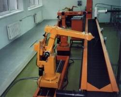
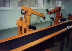
Photo 2. Robot cell
The basic elements of the cell are: two co-acting robots equipped with changeable sensors and tools, a conveyor belt, a vision system, a maze and control computers equipped with research-oriented control software. The cell elements are presented in Photo 2.
![]() Industrial robots
Industrial robots
There are two electric industrial robots (ABB IRb-6), manufactured in Poland. Although the mechanical part of the robot was constructed in early 70's, it is still in ABB offer. In Poland it is produced as IRp-6 industrial robot (Polish controller and supervisory system). IRb-6 is a 5 degree of freedom manipulator which can handle loads up to 6 kG, with repetition accuracy 0.2 mm. One of them is mounted on a linear track so it can be treated as a 6 d.o.f. robot in some cases.
The industrial robot controller consists of power electronics, joint controllers, safety control electronics, control computer and teach pendant containing a joystick to control robot joints. The controller program lets the user teach robot motions in Cartesian-Euler space and supervises its continous work.
![]() Bypasing the industrial controllers
Bypasing the industrial controllers
Purchase of industrial robots was only the start of what was required. The main problem, from educational and scientific point of view, was that the controller could not be modified by the users. They could only instruct the robot, by means of the supplied teach pendant language, how to move in the work area. Openning the control architecture was a necessity to allow the users to program at possibly every level of the control hierarchy, in order to investigate the controller or implement new control based e.g. on feedback from diverse sensors.
A specialized, parallel interface between a PC computer and an IRp-6 robot controller bus was made. The choice of a PC is justified by the fact that PC is perhaps the most common and best known platform for experimental development. The unique feature of the interface is that it enables PC to operate as a master on a robot bus. Thus the PC with such an interface board has a direct, fast access to the whole controller hardware. The data transmission rate is about 900 kB per second. For comparision, the real Ethernet speed is about 500-700 kB/s. The IRp-6 robot controller is now based on an open architecture. The sophisticated users can program the control hardware directly.
For the two robots two interfaces were made. Each of them is placed in a separate PC. Of the original industrial contoller only joint controlers are used. The PC computers can control robots on-line. What more, the cooperating PCs provide multiple plug-in-sites for commercially available special purpose circuit boards to integrate robots with sensors.
![]() Conveyor belt
Conveyor belt
A 3 m long conveyor belt is situated near the two robots in such a way that each of them can reach it easily. The conveyor is driven by the same DC motor type as used in the robots. An additional gearbox limits its speed. The motor servocontroller is situated inside the industrial controller of the robot which is not mounted on the track. Originally the conveyor motor was treated as the sixth robot "joint". However, in our application, there is a separate programmable control system for the conveyor. The useful feature of the conveyor drive is that it is possible to continuously change its speed.
![]() Ultrasonic matrix
Ultrasonic matrix
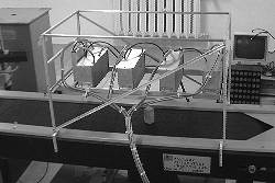
The ultrasonic matrix (Photo 3) is a device for 3D image acquisition. It consists of 40 ultrasonic distance sensors working on the common frequency of 150kHz. The matrix repeats the measurement 15 times per second. Each measurement consists of 10 frames in which four sensors act simultaneously. The matrix is located above the moving conveyor. The composition of measurements and positions of the conveyor yields 3D image of the observed scene.
The ultrasonic 3D image differs from the real scene, because of various distortions.
Our recent work has been focused on ultrasonic image restoration. This problem is related closely to the identification of the matrix, i.e. the determination of exact orientations and positions of the sensors. The restoration must also take into account the blur and other distortions specific to ultrasonic measurements.
![]() Force / torque sensor
Force / torque sensor
One of the robots has force control capabilities thanks to a six degree of freedom force / torque sensor able to monitor generalised forces exerted on the end-effector. The facility consists of the Schunk FT65/5 sensor, the Schunk FTS controller equipped with the parallel interface to a PC computer and a self made library of functions written in the C language to collect and process the obtained sensory information. These functions are integrated with the research software controller which is responsible for the operation of the whole cell. Students can learn how to write programs that influence the force sensor and motor controllers.
![]() Vision system
Vision system
The grey-level vision system with two CCD cameras is installed within the robot cell. One of the cameras is stationary, mounted on a post over the conveyor belt. The second one is a little camera fixed to the robot wrist. The signals from the cameras are supplied to an image processing system. It is a PC based card with the Data Translation 2867 video processor and the library of C functins provided with the card. The Data Translation system can work simultaneously with up to four cameras. In order to integrate the vision system with the robot controller, many software functions have been prepared. They process the signals from the vision system and transmit the results to the adequate functions in the robot control system.
![]() Maze and a touch probe
Maze and a touch probe
The maze, shown in the Photo 5 and Photo 4, is situated in the work space of one of the robots. The maze is useful test bench for multiple experiments with robot control. It also enables practical use of sensors. Three kinds of sensors may be applied here: a 5-bit touch-probe, a force/torque sensor and the camera.
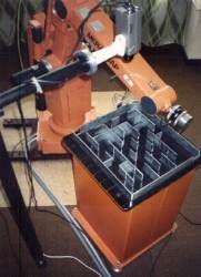 Photo 4. The robot uses the force sensor to find the way in the maze |
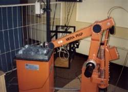 Photo 5. The robot uses the camera to find the way in the maze |
![]() Grippers
Grippers
There are several grippers which may be mounted on the wrist depending on the purpose of an experiment:
![]() Sensors
Sensors
![]() Multi robot research oriented controller (MRROC)
Multi robot research oriented controller (MRROC)
A research oriented controller for robots equipped with sensors was implemented several years ago. It can control a multi-robot system with any number of effectors and sensors. It is composed of a large, self-made robot control library of procedures and processes which fit a general structure of multi-robot system. Depending on the task, only some of the software blocks are fitted into the control structure that will execute the task. C was used as the language platform for the library. A distributed computing architecture is utilized to implement trajectory planning algoritms, executing e.g. force controlled motion and solving the manipulator kinematics. The control system consists of several concurrent processes: robot control processes, human interface processes, virtual sensor processes.
The capability is provided to modify or rewrite almost any part of the control system. This implies an open architecture and full user programming capability. Students and researchers can immediately focus on the subject of implementing theoretical results such as new control algorithms.
MRROC has already been the platform for verification of several research results. For example a PhD thesis devoted to trajectory planning algorithms for dual-arm system was experimentally verified. MRROC enabled motion planning and control for multiple cooperative arms. In the experiment two robots transferred a rigid object (Photo 6).
![]() Robotics cell hardware control architecture
Robotics cell hardware control architecture
There are several PCs which are involved in supervising the cell : PC386/33MHz and PC486/100MHz, directly linked to robots and one PENTIUM/100 MHz that increases the overall computing power. The PC386 and PC486 computers perform low level robot control and also communicate with the ultrasonic sensor via the analog/digital card and with the force/torque sensor via the parallel interface. The PENTIUM computer hosts the image processing card enabling thus images to be incorporated into the robot control algorithms.
All PCs are configured as a LAN. It is no obstacle to enlarge the computing power by adding new LAN computers.
![]() Real time operating system
Real time operating system
All PCs in the robot cell work under the supervision of the real-time operating system, called QNX. It is a distributed operating system which implements a fast and easy network based real time operations. MRROC is composed of real time concurrent processes executed by several QNX computers. The user working on one computer console can initiate the work of all cell computers.